14 May 2021

Can You Paint with All the Colors of the Cyber-Wind?

I've been hard at work (yes it's still called work even if you think it's fun. Don't let anyone convince you otherwise) on ShipBasher and my untitled procedural generation project, but today I want to digress a bit and blather on with opinions I have on the cyberpunk genre, as a bit of a follow up to my post from a while back about BLAME! (or perhaps more accurately a tangent from it).

It'd be weird if today, in 2021, I didn't mention the recently published game Cyberpunk 2077, so I'll get that out of the way first. As far as my cursory research indicates, its name is due to it being an adaptation of a pre-existing and much older tabletop RPG system known simply as "Cyberpunk" - so if, like myself, any of you are mildly irked that the name of the genre itself was co-opted for a single commercial product, I suppose it's only proper to consider the developers of said tabletop system the true guilty party. Of course most of you I imagine see the name issue as insignificant, particularly as overshadowed by the franchise's more general effects on the genre and its associated fandom.

Lest I sound negative and bitter, I first want to give credit for the positive impacts I believe it had. First and greatest, it got a lot of people - a lot of gamers, at least - using the word and thus talking about the genre. More visibility usually means more fans, and more fans are necessary to keep the fandom alive. Second, I think it illustrated, and reminded the industry at large, that the ancient truth still stands today - a product can be profitable whether it's singleplayer, DRM-free, single-purchase, or whatever, if it's made with love. Maybe that sounds empty and wishy-washy but hang on a moment - I think it's fair to say that consumers can tell when creators put love into their work, and as a result they enjoy it and thus it sells. It wasn't the publishers, of course; it was the developers. In interviews and social media they consistently brought up hardships but rarely if ever claimed to dislike the game itself or cite wanting to work on some other project as one of their sources of grief, and their positive statements were commonly centered on the game itself and where along the way they felt pride. And yes, perhaps something made by experts in profitability but devoid of passion or soul can outsell it, but it doesn't change the fact, established afresh, that something done with loving care can be successful even in an environment saturated with hollow titles the way the modern game development industry is.

Where the thing fell flat was in the way it portrayed what, specifically, the creators loved within the cyberpunk genre. Whatever it actually was, the game made it seem as though it was the look and none of the deeper themes or messages. In fact it did so well as a result of said love for the look that I suspect it drew in a lot of fans who were unaware there even were any deeper themes or messages, which would be sad because they do exist and are both beautiful and important. That's universal within the cyberpunk genre as I see it, but exactly what those themes and messages are is what I want to examine today. I don't want to make this post about Cyberpunk 2077 any more than it needs to be (it's already taken over enough of the industry, right?), so I'll try to avoid bringing up which things it tragically missed or handled poorly in favor of just pointing out what's there and leaving it to the reader to notice the gaps.

For some time now the term "cyberpunk" to me has actually meant a collection of at least three related but not quite equivalent genres, each of which carries its own general set of philosophical ideas (though there is significant overlap) and vague color scheme; thus I refer to them by colors, hence the title of this article. I'll dive into each in turn, but to give a primer, the colors are as follows:

Pink Cyberpunk: Cyberpunk 2077's sub-genre, so named for featuring distinctive pink colors that the others don't. This appears in neon signage, gaming PC case lighting, and car decorations for example. Not everything is pink and other colors (such as yellow) may predominate, but there's certainly more pink here than in any of the below sub-genres.

Green Cyberpunk: The Matrix's sub-genre, so named for its characteristic green tinge. "Matrix code" is the most obvious example, but others exist including the back lighting of retro-style computer displays and often even the tint of metals and entire environments depicted in this sub-genre's media.

Brown Cyberpunk: The best example in my mind of this is Battle Angel Alita - the manga and OVA, not the live-action movie (not that I disliked it). Brown and tan are commonly seen in rust, sand, engines, armor, and metallic surfaces in general.

Gray Cyberpunk: Manga artist Tsutomu Nihei is a master of this sub-genre. Color is minimal, giving way to concrete, harsh white lights and black shadows, and gray metal. I think this is my personal favorite sub-genre.

I foolishly thought I'd cover all of these in one post - and maybe I could have - but I'm tired now and splitting it up gives me the opportunity to equally foolishly try to feature each one in a post of its own, so I'll leave off here for now.

P.S.: Before I conclude discussing all of the colors together, I want to point out a few things. As I mentioned, there is overlap. Each color seems to feature a few philosophical ideas more prominently than the others, but many ideas are shared and a setting or story that fits one color better than another may yet explore ideas characteristic of another. A single setting or story can also meander among colors, exploring the ideas of one and then another and changing its aesthetics along the way. Some settings have the look of one but focus on the ideas of another. This "system" is really only the result of me finding patterns that I can use as a framework for analyzing the spectrum of cyberpunk aesthetics and ideas.

24 April 2021

Procedural Chunk-Based Universe Part 9: Across this New Divide, Part 2

Picking up where my last entry left off: Once I had the basic ingredients for an adjustable bridge whose segments could change angle and length, the next task was to give these to an algorithm and have it use these features to construct a bridge of whatever shape and size would be needed.

Computers, and in turn algorithms they run, are fundamentally mathematical objects and thus - sigh - I resigned myself to digesting a heavy serving of math, specifically trigonometry in this case. Each end of the bridge would be a segment that had to face a particular direction - that of whatever connected to the bridge at that end (e.g. one of a pair of doors). Thus, in mathematical terms, each end comprised a point in space (I was only worrying about two dimensions at this point) and a direction vector which had to be followed for at least the length of one bridge segment. By combining these direction vectors with a line connecting the two points, I could create one side and two angles. My task, therefore, reduced to its most basic mathematical formulation, was to complete a triangle given these ingredients, a situation often denoted as "ASA" for "Angle, Side, Angle" in academic settings:

Points A and B are the bridge's end points and arrows indicate the direction vectors; combined together, these constraints yield the rest of the figure including point C and the various angles labeled with lower case letters.

Having drawn this triangle, I considered how I would use curved segments to accomplish the change in direction. I couldn't rely on a single corner to do this, because any curved segments would change their overall lengths as their curvatures were adjusted, and I had set them up in such a way that they could be constructed with various shapes and amounts of curvature. If I started building a curve at one end, by the time that curve was in alignment with the direction needed on other end, the end of the curve would very likely be out of alignment with the position of the other end such that a straight segment couldn't properly connect them.

Fortunately there was a way out! Curves facing opposite directions had the potential to cancel out these offsets in position if they curved by the same amount. In other words, if I split the curved part of the bridge into two halves, an isosceles triangle, having two corners that have the same angle, would permit me great freedom in how the curves were actually shaped while maintaining the certainty that the ends of the curves could line up with both ends of the bridge. In the above image, triangle ACD is an isosceles triangle, in which the exact angles are unknown but angles b and c are known to equal each other. Thus, if I could find point D, I could simply build a bridge connecting A to D and then easily connect that bridge to B using only straight segments.

After doing some calculations using Al-Kashi's Law of Cosines, I was able to find places to put the curved parts of the bridge and then align them with the end points and with each other:

In my experimental setup, a bridge is being generated to connect the platforms at the top of each of these two cylindrical towers. Note how each curved segment here is attached at one end to the corresponding point in the isosceles triangle, rather than being centered on it. The goal, after all, is to have the ends of the bridge and its constituent segments aligned; the positioning of the centers of the pieces is of little importance.

Because the two curved segments curve the same amount in opposite directions, the offsets that occur at their end points cancel out and thus they are in alignment with each other. So far I've only experimented with a single pair of curved segments; but the system is designed with the concept of chaining multiple curved segments together in mind, in case individual curved segments are unable to curve far enough to achieve a full alignment on their own.

Now it's a matter of repeatedly spawning straight segments in the gaps to fill them in. This process makes use of the same Node Attachment system I implemented before that was used for manually constructing and later automatically generating levels. To minimize complexity for the sake of performance, first a series of straight segments is attached, continuing until the remaining gap is within the extension range of a single telescoping segment.

In the first draft of this system, only one type of "normal" straight segment was included, but recently I have implemented an array of segment templates from which to choose. The system iterates through this array, sorted from the longest template to the shortest, until it finds one that fits in the remaining gap without extending too far; thus the final bridge ends up being built out of significantly fewer total segments, which should improve performance overall.

For the sake of clarity I have colored the two segments yellow and green. First the longer yellow segment is attached in the gap, then the shorter red segment. Since the remaining gap is less than the maximum length of a single telescoping segment, no more "normal" segments have been inserted.

Now that a single telescoping segment can span the remaining gap, it is inserted and its length is adjusted to match the remaining distance:

The telescoping segment consists of a base (red) and an extended section (yellow), which slides in or out to match the desired total extension distance.

The second gap is then filled in the same manner as the first:

Diagram of the full construction process. For clarity I have shrunk the visual models of the segments slightly to create small gaps.

This system has served my purposes quite well so far, and I have compiled an interactive demo which is available on my itch.io page. In the demo the bridge construction process is set up as a coroutine with a small delay so that one can watch the bridge form.

It does have some constraints, though. It can only build bridges if the triangle depicted above can be formed, i.e. some point exists in between the two end pieces toward which both pieces are pointing (point C, even though point C itself is not directly used in the calculations). If, say, both ends are pointing toward one another but offset by some amount so that the bridge would have to curve in two directions (a sort of "S" shape), a bridge is not formed. Also, naturally, a bridge cannot be formed if the end points are facing away from one another. In the future, it should be possible to address either of these situations, if needed, by chaining two or more bridges together.

The ability this system provides to connect arbitrary locations (if they meet the aforementioned constraints) is valuable for both the 3D chunk system I discussed (for connecting doors between neighboring chunks) and the level generator I discussed before that (for creating closed loops). My goal is eventually to have all three of these work together to create a system capable of generating a limitless interconnected network of traversible spaces. I expect it to be just as complicated and difficult as it sounds, and I look forward to sharing many more of my adventures along the way.

23 April 2021

Procedural Chunk-Based Universe Part 8: Across this New Divide

I remember black skies, the lightning all around me. I remembered each flash, as time began to blur, like a startling sign that fate had finally found me... and your voice was all I heard. Did I get what I deserve?

SO GIVE ME REASON! To prove me wrong, to wash this memory clean, let the thoughts cross the distance in your eyes! Give me reason to fill this hole, connect the space between; let it be enough to reach the truth that lies across this new divide...

Sadly (or perhaps happily, if we're being honest), this post actually has nothing to do with Linkin Park or the Transformers franchise.

My earlier post "Going in Circles" detailed at length how my random level generator is able to piece together rooms and passageways into a tree structure but is unable to create cycles or loops that allow multiple paths from one area to another. I explained how this was important for game level design and then left off without having provided a solution.

What I did say was that my next step in solving the problem would involve adjustable pieces. The need for these arises from my insistence on not having the shape of the level be bound to a grid, as I detailed in my previous post about doors. When room prefabs aren't based on a grid, they can vary in dimensions in ways that easily and rapidly become unpredictable. A series of rooms can easily be generated that loops back toward an existing room's doorway, but it's all but inevitable that it won't line up in a usable fashion at all, let alone perfectly:

In this example, I've constructed a hallway that, due to the diagonal segments, can't align properly to reconnect to the central hub. A hallway segment spawned in the gap isn't able to fit without overlapping so badly it obstructs the player from moving past it.

How can I possibly connect the space between and bridge this new divide?

The solution I found was to implement "stretchy" segments that were able to telescope between a minimum and maximum length. By replacing some of the hallway segments with these, I gained the ability to fine-tune the dimensions of the hallway and align it precisely with the door:

One "stretchy" segment is placed at the end of the hallway and one in a perpendicular section, allowing the hallway to be adjusted on two axes.

Of course, however well manual adjustments may work, they won't be available during procedural level generation. I had to craft some kind of automated system that would find the correct alignment values and adjust the segments accordingly. Along the way I devised a way for segments to have a "secondary axis" for extension so that staircases (or in practice, ramps) could be used to join areas at different heights. The result was a surprisingly satisfying animation:

When given a target location, horizontal catwalks and ramps both have the ability to calculate the needed displacement and change their extension values accordingly so that their endpoints align with their destinations.

I didn't have to make it an animation, naturally - in practice these adjustments can be made in a single step when generating a level.

Nearly all the ingredients were in place at this point, but there was one more problem that arose - doors had no reason to end up perfectly oriented toward one another. Only because the angles happened to cancel out was it possible for me to achieve alignment in the above images, but while working on the random doors in my previous post, I realized that unless they were given random orientations as well as positions, the grid structure would still not quite be hidden - anywhere a player went, it would be easy to detect the orientation of the underlying grid cells by examining the orientations of the doors, and from there it would be easy to approximate the grid cells' locations. It sounds more subtle and complicated than it actually is when seen first-hand in a game world.

Thus in addition to segments that could extend linearly, I had to create a way for them to bend. As of this post I'm still working out a few kinks in this system, but what I have so far is able to calculate the direction in which a target position lies and then rotate the hallway to run parallel to that direction (which is slightly different from pointing straight toward it):


This functionality can be chained and combined with the existing telescoping functionality to create a self-adjusting bridge that does its best to maintain a connection between two points:


It's still far from perfect, and more importantly, it's of very limited use in this state. I can manually design a bridge that connects two points if it can, but the bridge still has no way to deal with the orientations of whatever exists at those points, and at this point I didn't have a system for automatically constructing bridges like this. In my next post I'll describe the solution I devised.

12 March 2021

Procedural Chunk-Based Universe Part 7: The Police, no wait I mean Eiffel 65, wait no not that one either...

My 3D chunk system, about which I have written before but honestly feel I should have covered in more detail by now, has a new feature.

As is surely obvious, the system creates and manages a population of box-shaped "chunks" that form a grid in one, two, or three dimensions as desired and can generate and store components of levels or environments, not unlike the chunks famously used by Minecraft for storing blocks and entities. Minecraft incidentally has another feature of particular relevance here, which is that when chunks generate terrain or features such as trees or villages, they are able to communicate with neighboring chunks about what they have generated. Thus it can be assured (if everything is working properly) that terrain will vary smoothly rather than abruptly changing at chunk borders, and if a feature such as a tree extends outside the boundary of one chunk into another, it can be assured that the blocks comprising it will be appropriately stored in the neighboring chunk rather than being abruptly cut off. It is easy to imagine myriad ways in which such coordination between chunks and their neighbors could be important.

A while back, as I was implementing the beginnings of this sort of communication in my own project, I created an experiment in which chunks behaved as cellular automata and recreated Conway's Game of Life:

As progress on the project continued, I foresaw that there would specifically have to be a way to ensure that travel was possible between chunks and their neighbors without having to leap a vast chasm or move through a wall. Whether the final use case be a labyrinthine parking garage such as in Find Your Car where doorways and ramps are needed, a sprawling cityscape where roads and bridges will have to connect, or a winding dungeon or cave system in which hallways or tunnels will have to lead somewhere, the concept of connecting points between adjacent chunks will be seminal. For convenience's sake I've been using the umbrella term "doors" for all of these despite some of them being a far cry from an actual door.

After establishing basic communication between chunks, I put together a few more experiments with different configurations of these doors. In the first draft, they were only generated at the centers of the chunk boundaries, forming a very obvious grid, but in short order I made it possible to generate doors with randomized offsets.

I actually spent a long time puzzling over how best to tackle potential problems with this concept - if a chunk generated a door leading outward into another chunk, wouldn't the second chunk have to then check on whether parts of it need to be regenerated (such as a wall blocking said door)? If so, wouldn't all doors have to be generated before things such as walls can be generated? But then, what if a chunk made a door and then another chunk tried to make a door that overlapped it - which chunk's door gets to stay? And what if a chunk generates a door leading into empty space (far from the player) and then another chunk generates later on and wants to put a wall or another door there?

To date my best solution has been to introduce a little bit of redundancy in exchange for making sure adjacent chunks always agree on where doors should exist: each "door" between two chunks is actually a pair of doors, each generated by and belonging to one of the two but existing in the same place. Later on when level geometry is being built, chunks can check for whether a door object exists at that position and forego spawning it accordingly.

All of this is pretty old news on my end, though. As I tend to do, I got this far and then did something else for a while. In retrospect I ought to have covered it on this blog earlier, but the reason I write this entry now is the new breakthrough I had in door positioning.

Before, even if doors were given random offsets, because they always existed on chunks' faces, the underlying grid structure remained visible, especially if I tried spawning a whole bunch of doors for each chunk. In many games this is acceptable or even desirable, but a priority of mine since the beginning was being able to completely eliminate the grid from the players' view. For instance, to reference Minecraft again, even though the world is made up of blocks, players don't see the world broken up into big square sections according to the chunk borders. Coastlines curve and hills roll in their blocky ways completely independent of those borders.

Recently though, as I was casually thinking about the project, it occurred to me that there is no real need for doors to actually exist on the chunks' faces. Despite being generated according to a given face, the actual spatial location of the door could be offset in its "depth" as well as within the plane of the face. Of course when I began to experiment with this idea, I immediately discovered a small issue: with this offset, the volumes in which doors could generate formed boxes of their own, and these would overlap. This might be a non-issue, but I had a bad feeling about it and still consider it undesirable at present. Fortunately, I realized that a cube (which is the basic shape of all chunks, though it may be distorted) is equivalent to six square pyramids that all "point" to the cube's center. This is easily illustrated by what happens when all of the cube's eight vertices are connected to the center:

Since any given face represents the interface of two chunks, it accordingly forms the shared base of two square (or rectangular) pyramids that together form an octahedron. Interestingly, this is not a regular octahedron, i.e. the familiar shape of the eight-sided dice popular in the tabletop roleplaying community or the approximate shape of a typical uncut diamond. This is significant because regular octahedra cannot fill a 3D space without either overlapping or leaving gaps, but the slightly oblate octahedra formed from slicing cubes can fill a 3D space, forming a mathematical object known by the very cool sounding name "Hexakis Cubic Honeycomb" or "Pyramidille" as coined by the aforementioned Conway:

The structure may be a bit difficult to see in this diagram but at least it looks cool. Click for the Wikipedia article explaining the concept in more detail.

By generating randomized points within a cube and then transforming them with a bit of vector math, I was able to produce sets of randomized points within these octahedra, which not only made for a few neat screenshots but allowed me to generate doors anywhere in 3D space without the generation volume belonging to any chunk face overlapping that of any other chunk face, which should help in avoiding potential problems such as paths leading to doors intersecting with paths leading to other doors when they shouldn't:

At this point the time felt right to make another demo, so for lack of any reason not to do so, I substituted trees and clouds for doors and used the newly revised system to generate a procedural forest. I had included the ability to constrain door offsets arbitrarily (as seen at right in the image above) and to spawn different types of doors for horizontal and vertical boundaries (e.g. to spawn staircases to serve as "doors" between a floor and those above and below), and I made use of these features to keep trees on the ground and spawn clouds as "vertical doors" in the sky:

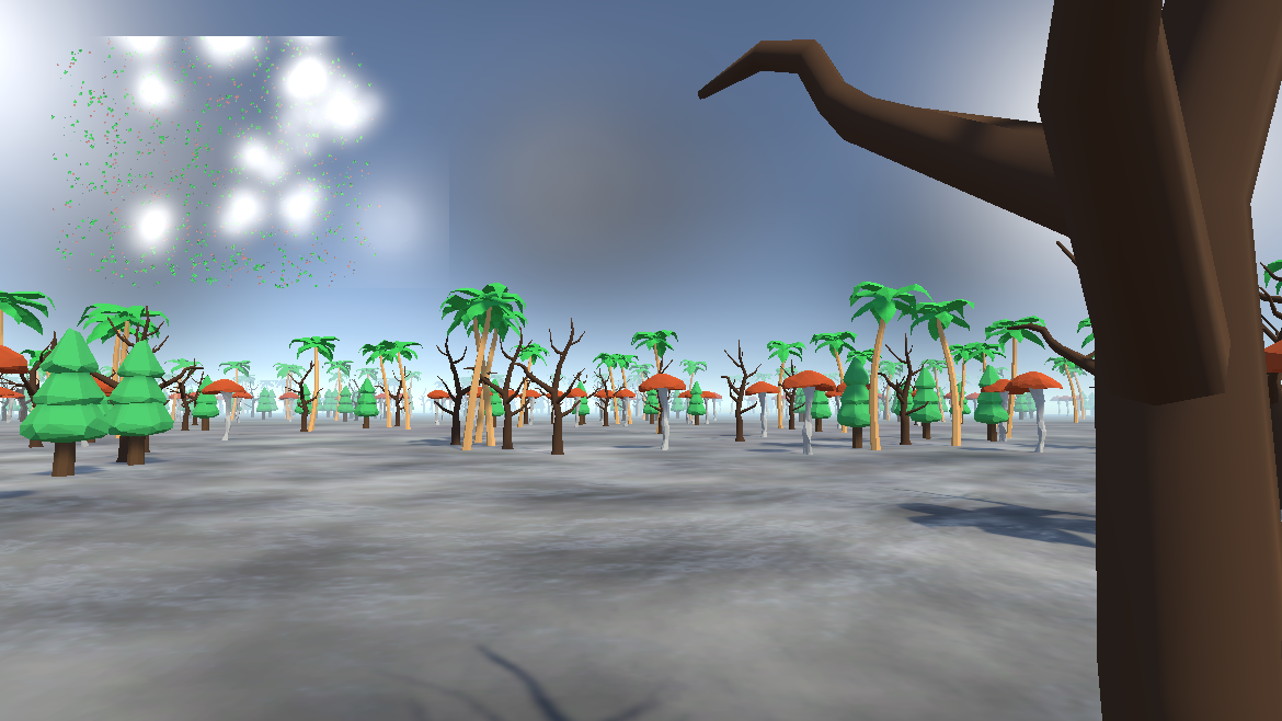
Perhaps now the jokes at the beginning of this article make sense. The minimap at top left shows how, despite being originally generated based on a grid, the final "door" positions appear completely random and organic. This demo is available to play on my itch.io page.

04 February 2021

Procedural Chunk-Based Universe Part 6: Going in Circles

Yes, it's been two and a half months since my last update. I suddenly got weirdly busy again.

Anyway, in my earlier entry "I Just Accidentally a Roguelike" I discussed a system I had concocted for assembling levels (or really any structure) from premade parts with attachment nodes. I mostly rambled on and on about the ComputePenetration function exposed in Unity's PhysX implementation and didn't illustrate the actual level generation process very clearly. To rectify that before I continue with new information, here's an image of a level the system generates:

This level is in the process of being generated. In the center is the starting room, which I placed manually. Branching off of it are randomly selected other pieces - in this case, simply small square rooms and straight hallways.

Observe how near the top right is a room with its attachment nodes visible. There are actually four here, though one is obscured. This and the other two green nodes are unoccupied and can accept new pieces, while the orange node is occupied by the hallway running toward the lower left. The hallway is not selected and thus its own attachment nodes are hidden, but they too are occupied, one by the selected room and the other by the second segment of hallway that in turn connects to the starting room. Every room and hallway in the level has its own set of attachment nodes in similar situations.

The level generator runs in iterations, during each of which it pulls from the set of all existing nodes, ignores those that are already occupied (This is not an optimal approach and I don't recommend copying it! This was an experiment.) and then performs roughly the same process as this one beautifully illustrated by Lived 3D:

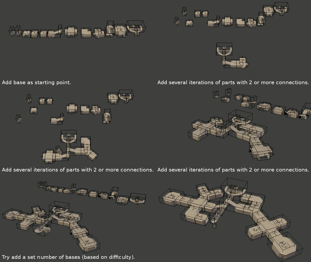
My version naturally has a few differences; for instance as I detailed before, I use a more precise collision detection technique, but on the other hand my system doesn't currently have the ability to automatically prune rooms in the event that it cannot add an end cap. For now this latter issue is easily accommodated by simply having a small "wall" piece that fits within the doorway of any room and can safely be inserted without risk of overlapping another room.

Both my and Lived 3D's systems work fairly well for levels of a limited size, but since I first made mine (two years ago already, wow) I've become aware of a major limitation they have.

In very basic mathematical terms, the structure usually described as a "level" in a game boils down to something called a graph.

No, not that kind of graph. I mean the type studied by mathematicians in the field of Graph Theory. In short, a graph is a data structure that follows these three rules:

  • Some number of vertices exist; a vertex is the intersection of some number of edges. This can be zero edges, and the number of vertices in the graph can be zero as well.
  • Some number of edges exist; an edge is usually a connection between two vertices, though in certain types of graph an edge can connect a vertex to itself or form a ray extending infinitely.
  • Edges can only exist where they are connected to vertices: no edge can exist "alone."

In technical terms, edges and vertices, while generally visualized as dots and lines in 2D or 3D space, do not need to exist in any type of space at all, and the positions at which vertices are drawn is immaterial. In level design, the physical space and the vertices' and edges' places in it tend to be very important, but for the moment I'm bringing up this topic because of a very important concept in graph theory - that of a tree. No, not that kind of tree. Observe these two graphs:

-

The first graph is called a "tree" because any vertex within it can be called the "trunk" or "root" and all of the edges connected to it "branches." In theoretical terms, the defining feature of a tree is that it does not contain any cycles, i.e. regions within the graph where it is possible to begin at a vertex, follow a path of connected edges, and return via that path to the starting vertex. Real trees tend not to grow branches in loops back into the trunk, after all. Note how in the second graph, two closed loops exist where one can create a path from one vertex back to that same vertex.

In level design, if one imagines rooms as vertices and doorways (or portals, or bridges, or whatever) between them as edges, pretty much any game level forms a graph and very often these graphs contain cycles. One game in which this is made very obvious is The Talos Principle:

The goal of this level is to solve a puzzle and thereby gain access to the area pictured and the T-shaped gold block therein. Once the player walks onto it and collects it, the fence at the right falls down, allowing the player to return to the beginning of the puzzle and leave through the front door instead of having to backtrack the whole way. This layout is necessary due to a design choice by the developers to have the puzzles be accessed in a non-linear fashion and all connect to a central hub. The underlying graph structure is also easily visible in many games via an overhead view of the level layout, as illustrated on Jared Mitchell's blog in regard to the game Amnesia: The Dark Descent:

Many level design tutorials exist that refer to graphs and cycles in this manner, and there are strong arguments for why this is a major boon for many games.

The system I made, however, can only generate trees. Once rooms are added, it only checks to see if more rooms can be attached onto their attachment nodes, and it has no way to examine their spatial relationship to other rooms' attachment nodes to see if it's possible to connect a new part of the level to an older part and thereby form a cycle. Much of the time, this isn't even possible because the doorways of these rooms won't line up with those on existing rooms. Alignment can be assured, or at least made much easier, by restricting level generation to a grid, as many games do very successfully, but I'm interested in exploring ways to keep the level free from grids wherever possible, meaning that the positions (and orientations) of attachment nodes can be highly variable and will almost never align perfectly by chance. Examining the first image in this post, for instance, reveals hallways that end in walls or converge in a way that seems like they could connect, except that there is no connector piece available that would fit in that space and complete the connection.

Therefore, in order to achieve this functionality, I've set out to engineer ways to make level pieces more flexible so that they can move their own doorways (and attachment nodes) to align with those of other pieces. I plan to go into more detail on the strategies I've begun to explore in a future entry.

19 November 2020

ShipBasher Development Log 15: Chad Space Elevator


Silly and critical memes aside, I took a break from writing code and mucking about in the Unity Editor to play around with some models and textures. ShipBasher is going to need modules that look they belong on epic sci-fi and fantasy spaceships like what we're used to seeing in Star Wars, Star Trek, The Expanse, and other popular franchises that feature spaceship combat. What it currently has is not that, and sadly I've failed to find any asset packs that really feel right in this respect so I don't even have the option to just buy some instead of making them unless I want to compromise on the final look.

I started blocking out a new generation of basic pieces in Blender such as fuel tanks, rocket engine nozzles, and the all-important crew habitation ring. While the majority of fictional spaceships opt for magical gravity of some kind (even The Expanse uses unrealistically efficient torch ship designs to pull it off), I would enjoy it if in some small way this game could help show the world how sci-fi can remain exciting while being a little more realistic in this department. Movies such as 2001: A Space Odyssey, Passengers, and The Martian helped, but none pushed very far into the gratuitous epic spaceship battle genre and that's where I want to contribute. Thus at least for now I mean to include things such as habitation centrifuges.

It's probably already familiar to most people who would be reading this and it's a simple concept at first: put the crew in a big hoop that slowly rotates around its axis, and the centrifugal force will be equivalent to gravity, helping them stay healthy on prolonged space missions:

In this screenshot from Nier: Automata, the space station known as the Bunker has a large ring that rotates. As 2B stands on the outer surface of this ring (i.e. floor), she perceives centrifugal force pushing her toward it, which feels the same as gravity pulling her downward and has the same physical effects.

When I started coming up with ideas, I discovered I had a problem to solve: there would occasionally be a need for someone to move between the artificial gravity ring and the rest of the ship (for example to access the engines to perform maintenance), and there were constraints on how this could be done:

  • I don't want people to have to exit the ship, whether in a dinghy or in an EVA suit, in order to get between sections. Ideally the elevator transferring them will remain inside the ship's hull at all times so that it needn't worry about repeatedly docking or dealing with radiation or debris from outside.
  • The whole ship shouldn't be required to rotate, as this would pose unnecessary difficulties for docking, tracking targets, and staying structurally sound: on a rotating object, centrifugal force is greater for parts further from the center, so anything that extends too far out will be under a lot of constant mechanical stress, meaning the ship will have to be bulky to avoid breaking apart.
  • The ring has to be able to "stack;" it should be possible to construct a ship with two or more rings in sequence, meaning there has to be a stationary attachment point on both ends of the ring's central column.
  • The rest of the ship must be able to connect to form a solid piece. If the elevator shaft rotates, and the elevator passes through the hull of the central column, then as it rotates it will sweep out a disc that completely separates the front and back portions of the ship.
  • Ideally this will be accomplished with a minimum number of moving parts and airtight seals, and any seals should be as small as possible to minimize friction and leakage.
  • The elevator has to be able to stop and wait at either end for any amount of time (in case someone is slow or has a lot of cargo to move), so junctions shaped like arcs in which the elevator can only spend a portion of a full rotation are not viable.

Based on these "rules" I eventually came up with this design:

  1. The passenger can enter the elevator (red) in the central column, where there is no rotation and thus no artificial gravity. The elevator is stationary at this point.
  2. The elevator passes through a stationary opening (not visible) connecting the central column to the inside of the bearing (yellow). Once inside the bearing, the elevator begins to move sideways and follow the circumference of the bearing, thus beginning to impose artificial gravity on the passenger.
  3. Once the elevator has matched its speed and position to the shaft (green), it enters the shaft and moves toward the outer ring. The bearing, shaft, and outer ring rotate together as a single connected unit, so the elevator does not need to perform any special alignment and instead behaves much like a familiar elevator on Earth from this point.
  4. The passenger exits the elevator into the outer ring and experiences artificial gravity. In order to move to the central shaft, the elevator can simply repeat this process in reverse.

Hopefully that wasn't too hard to follow. I could perhaps make a video about it later to make things clearer. This is the best design I've managed to conceive so far, fulfilling all of the constraints I identified. The only drawbacks are that it requires a large movable airtight seal between the inner surface of the bearing and the outer surface of the central column at the point where they meet, and the elevator has to be able to move in multiple directions and thus disengage and re-engage with multiple tracks as it travels. On the plus side, all of the elevator's movement occurs inside a pressurized space, so in the event of a breakdown it should be relatively easy to access and repair; and the elevator does not need to be able to park and wait while traveling through the bearing, so some of the space inside the bearing can be used to house motors (to maintain and control the ring's rotation) and other hardware.

While working this problem I tried to look for existing solutions and research on the topic, but alas, submitting the terms "space" and "elevator" in a query to a major search engine today causes a flood of results about the popular concept of a Space Elevator used for transit between Earth's surface and orbit, which while exciting, was not useful for this problem. One relatively helpful page I encountered was the extensive article on artificial gravity at Project Rho's Atomic Rockets website, but even this had little to say about the mechanics of transit in and out of the rotating sections of ships (or stations). If anyone has thoughts, or knows of existing research on this topic, please share it because I surely can't be the only one to be considering it and I'm eager to hear what other approaches have been explored.

17 October 2020

ShipBasher Development Log 14: The GPU Bullet Collision Saga, Episode 4: Conclusion...?

Having solved The Big Problem®, I was afforded no respite before having another problem to address. I noticed along the way that the testing code I had added to draw debug lines for all of the bullets that had entered bounding spheres was displaying a different set of bullets than the bullet rendering script was displaying. When I sucked up the performance impact and had the rendering script draw debug lines for every bullet in existence, I found something worrisome: all of the visible bullets were in fact behaving as they should and appearing in their correct locations, but a fair chunk of the bullets that had been fired were invisible!

I temporarily disabled stretching for the bullet sprites and made them really big so it was obvious which were being displayed properly and which only via debug lines (tiny blue dots).

At first I figured that some conditional statement or other was hiding bullets, so one by one I tried disabling all such checks. I even made the system draw red debug lines for inactive bullets. I had no luck.
Then I figured maybe something was up with the collision system. Fortunately that already has a simple Off switch, but it turned out that wasn't it either.
It did turn out that, while I didn't bother counting them myself and don't expect anyone else to do so, that exactly 2/3 of the bullets were invisible.
One may notice that 3 is the exact number of vertices in a triangle! HALF LIFE 3 CONFIRMED

Just kidding. The real reason this is relevant is because I was calling the sparsely undocumented function Graphics.DrawProcedural(). Because my geometry shader outputs triangles, I figured that when it asks for the MeshTopology argument, I should say to use triangles. Nope! Somehow that was causing the shader to be informed that two out of every three vertices were part of a triangle belonging to the first vertex and should be skipped by the geometry shader. Odd. Changing the MeshTopology argument to specify points (individual vertices) fixed it.

So yeah the moral of the story is that if you're drawing a point cloud using Graphics.DrawProcedural, use MeshTopology.Points. Hooray! Now my system draws three times as many bullets with one simple change in code and no significant change in performance! Here's how the system looked after all the recent improvements:

The captions in the image should be fairly self-explanatory. I can stretch the bullets based on their absolute world-space velocities or their velocities relative to the camera or some other object, I can spawn particle effects at their precise points of impact, and when the bullets ricochet they finally do so based on proper reflection vectors and I can specify how much of their original velocity to maintain and how much to randomly scatter. There is a tiny amount of imperfection in the impact positions still, but I feel that I've refined it as much as I need for the time being.

Here's another comparison, this time showing all of the iterations thus far:

Observe how, as the camera moves in order to maintain its position relative to the target ship, the purple bullets stretched according to their absolute world-space velocities appear to stretch in the wrong direction, whereas the cyan bullets appear much more correct. It's not shown above, but I can also have the cyan bullets maintain some portion of their forward velocities and penetrate into the target rather than bounce. This could be useful on some kind of powerful railgun that can punch through armor plates to damage modules inside a ship.

Also note that I finally fully implemented the option to have bullets become inactive upon striking a module, as I expect will be the case for most bullets in the final game. And look! I even got bullet damage working:

With all these kinks worked out, my next task was optimization. When I originally cooked it up, even with all its flaws, the GPU Bullet System could handle over 100,000 bullets on screen at once before any noticeable performance drop. At this point? Not so much.

The bulk of the problem is that the GPU can easily draw tons of identical sprites, but communication between the GPU and CPU is relatively slow, even on an integrated graphics chip. While the actual GPU and CPU are intimately connected, literally sharing a casing, in this architecture (if I'm not mistaken) the GPU stores its data in the same place the CPU does - the RAM. Thus, every time a buffer needs to travel between one memory region and the other, I lose several cycles of processing waiting for the data to be accessed from the RAM. Since each different type of bullet needs its own set of compute buffers, and at least one of these has to travel one way or the other up to four times per frame, having many different kinds of bullets in play at a time (as I do currently) leads to a significantly lower framerate.

Currently I'm investigating a few remedies to this.
By doing some optimization work in the code to reduce unnecessary operations and eliminate garbage generation wherever possible, I've sped it up by a noteworthy factor, but I still have several milliseconds' delay every frame while the CPU waits on data from the GPU. I've experimented with making this subsystem asynchronous, but that enables the data to arrive in an entirely different frame from the one during which I requested it and thus I have to deal with discrepancies in where the bullets are in the buffer I've received versus the main buffer, which in turn leads to grossly inaccurate results from physics queries and, once again, to my frustration, bullets floating through the target ship without touching it.
Next I think I'll investigate the possibility of only having one bullet manager script for the whole game and having each bullet within the buffer carry a bunch of extra data about what sort of bullet it is. Depending on how far I go with this, it could get very, very complicated.
There's also still the option of keeping it as-is. I'm open to suggestions on this.

Finally I leave you with a picture of what happens when I dispense with concerns about framerate entirely and make the system display ONE MILLION BULLETS!

There's no starfield background here - every single little white dot in the image is a bullet that the system is processing and rendering. The framerate is less than stellar in this situation but still surprisingly high, and I surmise that a more powerful GPU than mine would handle it easily.

13 October 2020

ShipBasher Development Log 13: The GPU Bullet Collision Saga, Episode 3: for(int i = r; i < r % z + r; i += r - z > i ? 1 : z % (r + z)){ z -= r; r += i; r = r % z + i > 0 ? i : r - z % r + z; z -= r; }

That "code" in the title isn't what's actually in the game (in fact I doubt it'd even compile, let alone do anything useful), but it is a caricature of how my code was starting to look to me at one point during the long debugging process I mentioned undertaking at the end of the last post.

See, I had also upgraded the compute shader one more time with a fourth compute buffer - this one representing bullets that the physics engine had confirmed actually did hit a ship. As of now I'm still just having them bounce off, but pretty soon I'm going to want them to stop existing, or in more precise terms as far as my code is concerned, become inactive so they stop being displayed and hitting things. Maybe sometimes I'll want bullets to survive and have secondary impacts (or penetrate through modules) but the option to deactivate bullets that have impacted is important. This buffer gets filled up on the CPU end of things, and then at the end of each frame, after the collisions have all been addressed, it gets sent to the GPU containing copies of all these bullets, notably including their indices in the original buffer so that the compute shader knows which of the original bullets have now become inactive.

Here, I'll recap with a flowchart that might help or might just make this all even more confusing:


Rounded rectangles represent the game systems related to GPU bullets; ellipses are tasks the systems can do, and the clouds surround the tasks belonging to a given system. The parallelograms represent the four compute buffers, and the arrows represent how each system affects each buffer or other system.

As shown here, the persistent data for the bullets is stored in the GPU's memory, rather than the CPU's as is the case for most of the game's data. Note how in order for the game to function, communication must occur back and forth between the CPU and GPU.

Because GPU code doesn't deal in pointers the way CPU code does, any time a data structure has to travel between one and the other, the data itself gets sent as a copy. Thus when, for example, the compute shader adds a bullet that has entered a bounding sphere, the bullet in the main buffer remains where it is, unchanged, while the new buffer entry is a copy of that bullet's data. In order to keep track of which data belongs to which bullet, I simply include an ID in that data. The first bullet that ever gets fired is given ID number 0, then the next 1, and so on up to the maximum number of bullets I allow in the game configuration, e.g. if I allow 10000 bullets then the last one is number 9999. After that, if I fire a "new" bullet, what actually happens is I overwrite bullet 0, which is bound to have either hit something or drifted off into deep space by this point. This is a common programming concept called a ring buffer or circular buffer, which is a type of object pool.

When a bullet enters a bounding sphere and a copy is added to the corresponding buffer and in turn sent to the CPU and the physics engine, unlike the bullets in the main buffer, that copy only exists for that frame. It's a trivial task for the GPU to regenerate it as it iterates through every bullet every frame anyway, so this has insignificant performance impact. In order for anything to happen, the physics engine must give a positive result when the bullet is evaluated that frame; otherwise it goes away when the buffer gets reset and thus nothing happens to the main buffer.

If a collision is detected, then that bullet's data is copied once again, this time into the buffer representing bullets that have hit something and must either be redirected or deactivated. Each type of bullet is handled by a corresponding instance of the bullet manager script and its own associated set of compute buffers, and for each type of bullet I can configure whether to allow ricochets or delete bullets after impact; based on which option applies, the data copied into the "impactor" buffer can contain a modified velocity or a flag indicating that it represents a bullet that should be deactivated. All bullets that have struck something are added to this buffer and then the buffer is read by the compute shader.

Because each bullet's complete data is copied every time, not only is its important position and velocity perserved, but also its original ID from when it was fired. Thus when the compute shader receives all the impacted bullets, it can match their IDs with the corresponding IDs in the main buffer and change those bullets accordingly, altering their velocities or deactivating them. In the end, bullets and the things that have happened to them persist frame after frame as long as they are needed.

I'm almost to the point where I explain the big problem I faced. There's just one more thing to explain. To prevent this becoming too much of a textbook page, here's another picture:

Another screenshot of my debugging process. The yellow specks are the debug lines for bullets that have bounced off the target ship and now entered the test ship's bounding sphere, which I temporarily made larger. You may notice something suspicious going on here that I'll address in the next entry.

Back on topic, I mentioned above that I assigned an ID to each bullet as it was fired. Unfortunately it's not quite as simple as slapping on a number during the firing function. If I were to individually update members of the compute buffer as bullets were fired, it would cause lots of little data packets to have to be sent to the GPU  - possibly lots every frame if the overall firing rate is high, as is the case with a rapid-fire gun or a large number of guns firing at once. Due to the way computers are designed, this would cause soul-crushing lag. Rather, the optimal way to go about his would be to gather up all the bullets that have been fired in a given frame in a nice little array and then at the end of the frame send one packet containing that array to the GPU - so that's what I did. Thus the firing function didn't count up numbers in the buffer itself, but rather the number of bullets that had been fired that frame. I called this number R.

What this means of course is that when I send the array of new bullets, I also need to tell the compute shader where to start changing bullets in its compute buffer, so I added a second counter value, which I called Z. Every time a bullet was fired, I would add one to R and to Z. At the end of every frame, once all the new bullets were ready to submit, R would reset to zero, but Z would remain as-is, tracking how many bullets had been fired ever, or at least since the last time I had made a full loop of the ring buffer. By doing math (see title) with R and Z, I could discern where in the compute buffer to start making changes and how many entries to update, and I could even check whether I had run past the end of the compute buffer and needed to go back to the beginning. Soon after I had implemented this, I had bullets happily whizzing out of the gun barrels frame after frame with no invalid array index exceptions or whatever, and I washed my hands of this and shifted gears to things like the collision detection that's been the focus of the last few devlogs.

But then I noticed something very, very strange. At high rates of fire, everything seemed perfect, but if I happened on a whim to switch to a low rate of fire, only a few bullets per second... bullets would float through ships unimpeded for a short time and then bounce off empty space as if it were the ship!

What's going on here?!? There aren't a lot of bullets visible so I drew some arrows to make it clearer - the bullets (blue crosses) are traveling up from bottom right, passing through the target ship, and then bouncing near the top and going off to bottom left even though there isn't anything at the top! No, there were no invisible or inactive colliders or anything simple like that.

When I first noticed bullets occasionally ignoring collisions, I figured it was the physics engine being unreliable and played around with how I did collision detection queries. No luck.

It seemed like the bounce was occurring not only at the exact rate of fire, but at the exact time firing occurred, so I investigated my weapon and module classes in extreme detail. No luck.

I even investigated my compute shader, geometry shader, and bullet rendering script. Swallowing the huge performance impact, I had Unity draw little blue debug lines on every single bullet all the time - those are the blue crosses visible above. No luck!

I was starting to go nuts and getting increasingly tempted to give up and resign myself to releasing a buggy game (okay I'm sure it'll be buggy anyway, but I should at least try to address the ones I do catch, right?)... but eventually I did figure it out. Notice that pink line? That's the debug line I have Unity draw to represent the new velocity a bullet is given when it impacts a ship - a line that only appears during the frame during which that impact occurs. The bullet bouncing off empty space is occurring exactly when, and only when, the next bullet actually strikes the ship!

It turns out that the second counter, Z, which tracks cumulative bullets, incremented after each bullet was fired and then was used as the start index for the compute buffer. Thus Z would begin at 0, I'd fire bullet 0, then Z would become 1. I'd fire bullet 10 and then Z would become 11. Thus when it was time to update the compute buffer, I'd say to start at index 11 rather than index 10 - every bullet would get assigned to the index just after its ID, and thus, as these IDs traveled back and forth during collision detection and eventually the compute shader compared the bullet IDs to the buffer indices, every time a bullet hit something the compute shader would go and edit the index matching that bullet's ID, i.e. the bullet just before - in other words, each bullet would bounce if the bullet just after it hit a ship. Yes that probably sounds a little confusing and it threw me for a loop (pun not planned but welcome) too.

Once I had that figured out, I went and re-did my counting system to be much more sensible. Now, R increments with every bullet, but Z does not - rather, Z stays put while the new bullets array is built and then increments by R afterward. Problem solved, though my head hurt.

Of course, after every bug there's another bug...

11 October 2020

ShipBasher Development Log 12: The GPU Bullet Collision Saga, Episode 2: There and Back Again, a Bullet's Tale

When I left off, I had just finished bragging about how I got information about bullets and ships to the compute shader so they could interact, and then I confessed that even with all the extra additions the bullets still couldn't have any effect on the ships in the actual game. Information about the bullets and ships was getting to the GPU and the compute shader, but no information was getting back from there to the CPU and the rest of the game's code; of most immediate importance was getting information to the physics engine.

I expanded the compute shader yet again to use a third compute buffer, this one representing bullets that had intersected a ship's collision sphere. This starts off empty and every time a bullet intersects such a sphere, it gets copied into the new buffer. The bullet manager is able to read this buffer every frame and thereby discover which bullets are inside a ship's radius and thus need proper collision checks. To start off I had Unity draw debug lines to represent each of these:

There are bunch of lines in this image, including the purple lines I have the script draw to vaguely indicate the bounding sphere of the target ship (the cylindrical object at center), but the focus for the moment is on the yellow lines. The blue crosses (which ironically I added later) are drawn by the "Point Cloud Renderer" script in charge of displaying the bullets. Every bullet that's inside the bounding sphere of the target ship is drawn with a yellow line running from its current position to its expected position in the next frame based on its velocity. Note that these are drawn, and collisions are handled, before the blue crosses are drawn by the rendering system, so the blue crosses generally line up with the forward ends of the yellow lines but sometimes are in different places as a result of a collision during this frame.

Now yes, for a very simple ship such as this target ship that only consists of one blocky module, it would be simpler to just send the collider to the compute shader and do all of the collision detection there, but in the finished game I expect ships to be composed of many modules and have odd shapes. Since the developers of PhysX (Unity's built-in physics engine) have already sunk a lot of time and expertise into doing precise and efficient collision detection, I intend to take advantage of the existing system here. Each yellow line not only depicts the bullet's projected trajectory, but traces the raycast used to query the physics engine for precise collision results. These not only include yes/no answers to whether the bullet struck something, but details about what it struck and how including surface normal vectors, the precise location of the impact, etc. In short, round-trip communication was now established and it had become possible to do proper game things like spawn explosion particles and apply damage to modules.

I also proceeded to take the "bouncing" placeholder code out of the compute shader and add a somewhat better bouncing function in the manager script. Bullets thus ricocheted off the ships' hulls and did so based on the surface normal vectors:

From left to right in the lower image: laser turret for reference; "old" turret without target leading (note how it misses the moving target); improved turret with instantiated prefab bullets; two different variations using the GPU Bullet System but without collision detection (orange and yellow - note how the bullets pass through the target with no effect); turret using GPU Bullet System and rough collisions based on bounding spheres (purple - note how the bullets bounce off in a scattered cloud); turret using latest collision detection features. The new system at this point caused bullets to reflect off the surface normals, but do so in a very "perfect" fashion so that they all came back in a nearly perfect single-file line.

After a few minor adjustments, such as allowing bullets to ricochet at reduced speeds (purple) and with some random variation in direction (cyan):

Things were looking pretty good, except that I kept occasionally noticing that a few bullets would still somehow manage to float effortlessly through the target ship as if it weren't there. I kept wanting to dismiss the problem as just a minor quirk, but looking objectively at the situation, when there were a lot of bullets flying around, the small fraction that didn't collide still made up a lot of bullets, too many to ignore.

I kept poking at this problem until it started to drive me crazy. I carefully examined debug lines such as those above, stepping through frame-by-frame in hopes of gleaning what made the non-colliding bullets special, and oooh, did I find quite a big problem lurking at the bottom of it all. Look forward to the depths of my despair frustration in the next entry.

09 October 2020

ShipBasher Development Log 11: The GPU Bullet Collision Saga, Episode 1: Spheres

I concluded the last log with a paragraph about how I planned to continue integrating my GPU Bullet System into ShipBasher by establishing round-trip communication between CPU-based physics code and a compute shader running on my GPU for bulk processing of bullets. As of now I've finally achieved this as well as uncovered and fixed some shocking bugs. The path here was quite a saga, so I shall recount it in parts.

Several years ago I started playing EVE Online and have gone back and forth between active play and long breaks ever since. I love many facets of the game and it's probably little surprise that it's one of the inspirations guiding my development of ShipBasher, both aesthetically and mechanically.

Because EVE Online runs on a single massive server cluster that has to handle tens of thousands of concurrent active players at times, there's no budget for careful, precise physics calculations when big swarms of ships start yeeting clouds of bullets at each other. As far as my research has led me to understand, the server instead abstracts away all the bullet motion and simply treats every ship as a sphere - a shape that can be fully defined with only four numbers, those being its position in each of three dimensions and its radius. With this knowledge, the server can get a fairly decent approximation of the ability of one ship in one place to damage a ship of a given size in some other place. Whenever a weapon fires, it crunches these numbers and a few others and determines what happens - all further detail is just visual effects.

All those little red, orange, and blue squares are indicators of player's ships. One can see the need for performance optimization.

I don't intend to approximate this roughly in ShipBasher, but I saw great potential in the idea of treating each ship as a simple sphere for coarse collision detection. I realized I could have every ship compute how big a sphere would fully enclose it, tell the GPU Bullet System what that value is, and thereby enable that system to easily differentiate between bullets near enough to a ship to be likely to touch it and bullets adrift in space unlikely to be touching anything. Presumably, most of the time the bullets about to hit things will be a minority of all the bullets that exist (since there's a lot more space not inside a ship than there is inside a ship in most circumstances), so if I can narrow those down and only do physics calculations for those, I can support much larger quantities of bullets without a much larger performance impact. The first step to doing this, of course, is to get those bounding spheres, which, like many things in programming, proved more complicated than it sounds.

Modules consist, in the game engine, of combinations of physical objects and visual objects, which don't necessarily (and usually don't) exactly match in shape or size. Most visual objects are "meshes," collections of 3D vertices connected with triangles, and most physical objects are "colliders," which are sets of equations that define geometric shapes and are invisible, but important for running simulations of solid objects. Calculating the exact radius of a collider is usually fairly simple, but requires a different strategy for every given type of collider that might exist in the finished game, and calculating the radius of a mesh is conceptually simple but very tedious. Fortunately, one thing that colliders and meshes have in common is that the engine uses axis-aligned bounding boxes as representations of their rough sizes. I could have used these instead of spheres, but it would have added slightly more work for the compute shader, and every bit of optimization counts in a system that might have to handle hundreds of thousands of bullets at once.

I investigated a few strategies for converting bounding boxes into approximate spheres and eventually settled on iterating through every collider and renderer (a visual object that has a bounding box - usually a mesh) attached to a given ship and, based on its relative position and the radius of its bounding box, incrementally calculating an approximate radius for the whole ship. This technique should be mathematically guaranteed to never give a result smaller than the "true" radius of the ship, but typically does overestimate slightly. Fortunately for my purposes, the smaller each individual module is relative to the ship, the more precise the overall calculation ends up being.

 I didn't actually need to include renderers at this point, but later on I expect to reuse the radius value in a few other parts of the game, and I want players to see a radius that is consistent with how big the ship actually appears to be.

With that part out of the way for now, I changed tack and started getting the GPU Bullet System ready to deal with spheres. I reprogrammed the compute shader to use a new buffer of spheres in addition to its existing buffer of bullets, and as a temporary debugging feature I rigged the bullet management script to generate some random spheres to feed into this new buffer alongside some random bullets (since the existing turrets are only able to target things like ships and modules, not imaginary spheres):

Not to be an overachiever, I didn't bother building a fancy visualization for the spheres, since they were temporary after all. I just had the engine draw some random debug lines based on the centers and radii of the spheres to give a vague sense of where their boundaries were. Also visible here are the debug lines and bullets from the old turrets, which I didn't bother disabling, but more importantly there are the white bullets spewing out in random directions. Note how most are radiating out from the origin, but a few are traveling other directions - these have struck a sphere and "bounced" (I put it in quotes because I didn't bother with actual reflection vector math and just made a crude approximation) off. Collision detection, hooray!

Next all I had to do was feed the compute shader with the real bounding spheres from the ships' actual positions and radii:

I had the wherewithal to turn off the starfield background at this point so the important things could be seen clearly. At left is the GPU Bullet System as it was before, flinging yellow dots into space to look pretty but do nothing else. At right is the new version. The target ship in the distance (as well as the testing ship in the foreground) has calculated its bounding sphere and added it to the sphere buffer as a 4D vector, in which the first three values are the position and the last value is the radius. Due to the way GPUs are built to deal with matrices and four-component colors (red, green, blue, and an "alpha" value typically used for opacity), this format is easy to implement and process.

The compute shader at this point had two tasks for each bullet: move it forward a bit based on its velocity if it is active, and go through all the bounding spheres to see if the bullet is inside one of them. This does mean that every compute thread is going to run through the full collection of all bounding spheres, as I haven't implemented any optimizations such as spatial partitioning, but considering that I don't expect there to be a huge number of ships active at once, I decided that a little inefficiency at this particular stage was a lesser evil than the extra complexity of some algorithm for picking and choosing which spheres to check. In fact, unless there actually are a huge number of ships, I suspect that my choice was in fact the optimal one here.

Once the compute shader had run, all of the active bullets had advanced forward and any bullets that touched a ship's bounding sphere had been detected. For the moment I simply had the GPU change their velocities to point directly away from the bounding sphere (that "bounce" I described above) so I could see that it was working, but all of the bullets were still confined to the realm of the GPU. They made it onto the screen, but no information about what happened to them made it back into the rest of my codebase, meaning that ships didn't know they'd been hit (nor did anything else, even the bullet manager script) and thus couldn't be damaged or otherwise affected. My next task (and the subject of the next entry to come) was thus to establish a line of communication from the compute shader back to the CPU and the scripts it was running.

Sorry this isn't a real post :C

I've entered graduate school and, as I expected, suddenly become far busier than I had been before, leaving no time to maintain my blog,...